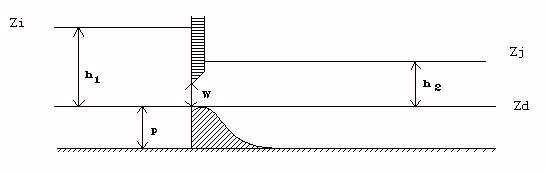
CEM88(D) : Weir / Orifice (important sill)
Weir - free flow
(\(h_1 < W and h_2 \leq \frac{2}{3} h_1\))
\(Q = \mu_F L \sqrt{2g} h_1^{3/2}\)
Classical formulation of the free flow weir (\(\mu_F \simeq 0.4\)).
Weir - submerged flow
(\(h_1 < W\) and \(h_2 \geq \frac{2}{3} h_1\))
Classical formulation of the submerged weir.
The switch from submerged to free flow occurs for \(h_2 = \frac{2}{3} h_1\), we then have:
\(\mu_S = \frac{3 \sqrt{3}}{2} \mu_F\) for \(\mu_F = 0.4 \Rightarrow \mu_S = 1.04\)
An equivalent free flow coefficient can be calculated:
\(\mu_{F} = \frac{Q}{L \sqrt{2g} h_{1}^{3/2}}\)
which makes it possible to evaluate the degree of flooding of the threshold by comparing it to the free coefficient \(\mu_F\) introduces. Indeed, the master coefficient of the structure introduced is that of the free weir. (\(\mu_F\) close to \(0.4\)).
Orifice - free flow
(\(h_1 \geq W\) and \(h_2 \leq \frac{2}{3} h_1\))
We take a formulation like:
\(Q = \mu L \sqrt{2g} \left( h_1^{3/2} - (h_1 - W)^{3/2} \right)\)
This modeling applies well to large rectangular orifices.
Continuity to free surface operation is ensured when:
\(\frac{h1}{W} = 1\), we then have \(\mu = \mu_F\).
Orifice - submerged flow
There are two formulations depending on whether the orifice is partially submerged or totally submerged.
Partially submerged flow
(\(h_1 \geq W\) and \(\frac{2}{3} h_1 < h_2 < \frac{2}{3} h_1 + \frac{W}{3}\))
\(Q = \mu_F L \sqrt{2g} \left[ \frac{3\sqrt{3}}{2} \left( \left( h_1 - h_2 \right)^{1/2} h_2 \right) - \left(h_1 - W \right)^{3/2} \right]\)
Totally submerged flow
(\(h_1 \geq W\) and \(\frac{2}{3} h_1 + \frac{W}{3} < h_2\))
Classical formulation of submerged orifices, with \(\mu' = \mu_S\).
Orifice weir operation is represented by the equations above and Figure 19. Regardless of the type of flow under load, an equivalent free flow coefficient is calculated corresponding to the conventional free orifice formulation:
\(C_F = \frac{Q}{L \sqrt{2g} W (h_1 - 0.5 W)^{1/2}}\)
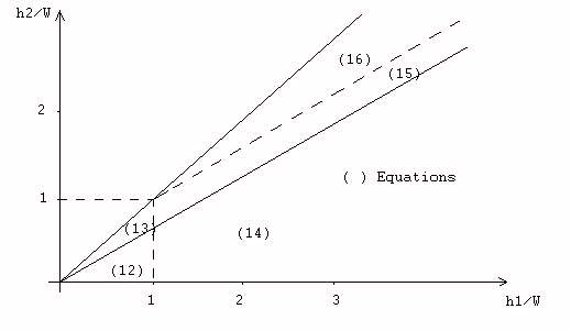
- (12) : Weir - free flow
- (15) : Orifice - partially submerged
- (13) : Weir - submerged
- (16) : Orifice - totally submerged
- (14) : Orifice - free flow
Figure 19. Weir - Orifice